Adjustment of fodder corn harvesting machine: the second part of adjustment of feeding unit and cutt
JAVID KESHT LEYZERI COMPANY
Adjustment of fodder corn harvesting machine
The fodder corn harvesting machine is one of the complex agricultural machines and if it is not properly adjusted during harvesting, it will not perform its operation properly. In the following, while introducing the building and specific features of the machine units, their settings are explained.
feeding unit
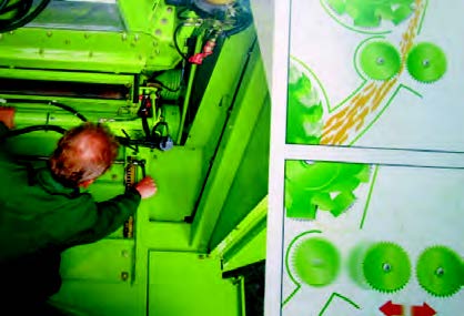
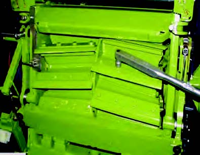
The feeding unit consists of a number of rollers that are adjacent to each other and two on top of each other. The upper rollers rotate opposite to the lower rollers and are floating in their place so that they can change their position with the change in the volume of the input fodder. The speed of the feeding rollers can be adjusted in three positions using its drive gear box.
In the picture below, you can see the gearbox for adjusting the feeding speed of the feeding rollers.
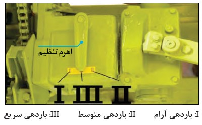
Note: Changing the speed of the feeding rollers should be done when the nozzle stops or moves at a slow speed.
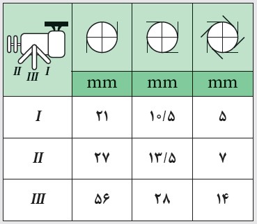
Changing the feeding speed of the feeding rollers has an effect on determining the size of the cutting length. In the table below, the size of the cutting length is specified in relation to the condition of the feeding rollers.
Adjusting the rotation direction of the feeding rollers
The transmission of power to the feeding rollers is done by a gear box called a reverse gear box. (Figure below) Using this gear box, the rotation of the rollers can be stopped or reversed.
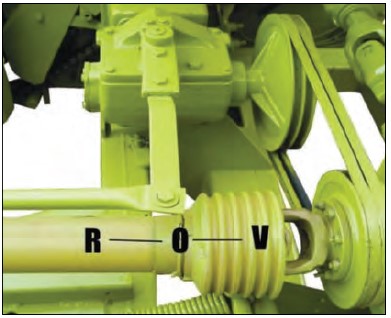
Stop status: O
The state of moving forward: V
Fodder return status: R
This action is to prevent harmful substances from entering the machine and to adjust the feeding rate of fodder, also in cases where the device is under pressure due to excessive fodder entering the cutting unit and accumulation of chopped fodder in the conductor tube of the device, by reversing the direction By rotating the feeding rollers, the forage does not enter the cutting unit, and the previously chopped forage is pulled out, making room for new forage.
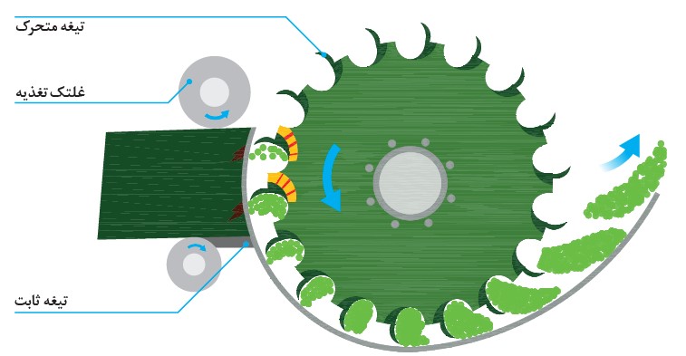
cutting unit
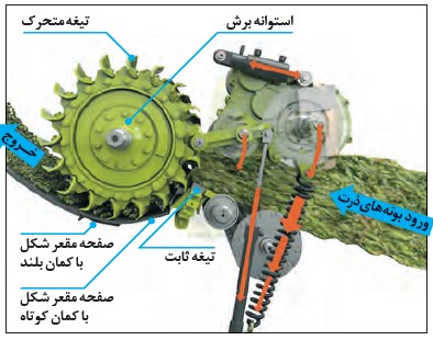
After leaving the feeding unit, the corn plant enters the cutting unit. The cutting unit consists of a rotating cylinder on which a number of blades with equal distance and angle are placed. The angle, distance and number of blades on the cylinder can be adjusted. With the rotation of the cylinder and the passing of the moving blades in front of the fixed blades, the input materials are cut to specific sizes. The cut material passes over a concave plate with a short arc and then passes over a concave plate with a larger arc and exits the cutting chamber.
In two-row choppers, after leaving the cutting cylinder, the cut product enters the discharge pipe directly and is transported to the machine through the discharge pipe, but in self-driving choppers, the material after leaving the cutting cylinder enters the cob part of the chopper or directly enters the accelerator part. And then they are guided into the transporter by the discharge pipe.
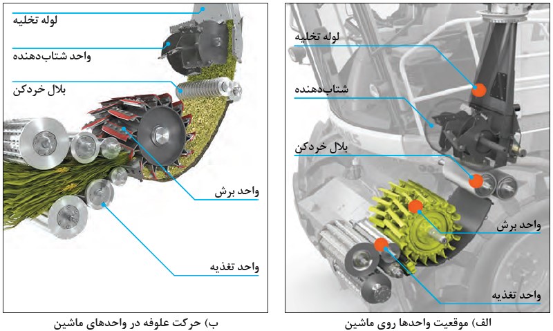
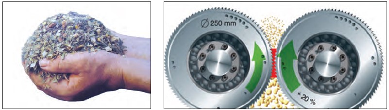
Cob chopper: When the corn plant enters the cutting cylinder, the corn cob is cut into equal pieces like other parts of the corn, but the cob seeds, which contain protein and nutrients, also remain on the cob wood, which is poorly digestible for livestock. The cob chopper breaks up the cob wood and splits open the kernels to disperse the protein into the forage.
This unit consists of two saw-toothed rollers that rotate with a 20% difference in speed relative to each other and separates almost every grain from the cob.
You can see the rollers of the cob crusher and its effect on the cob seeds in the figure below.
In harvesting other silage fodder such as green grains, beans, pulses and alfalfa, the cob shredder unit should be removed from the circuit and the cut product passage chute should be used instead.
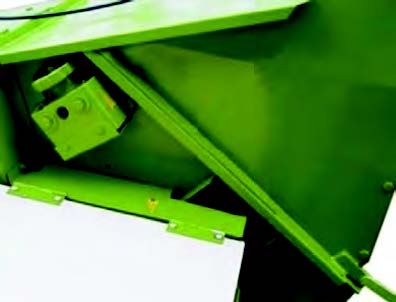
Removing the chopper from the circuit
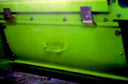
Gutter passing the cut product
The cutting unit has several important settings:
Fixed blade adjustment: The fixed blade in all types of fodder corn harvesting machines should be adjusted so that its distance from the moving blades is 0.2 mm at the cutting point, which you can see in the picture below.
Adjustment of moving blades: the distance, angle and number of moving blades on the cutting cylinder can be adjusted.
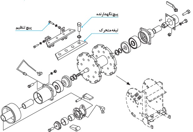
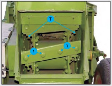
You can see the components of the two-row corn cutting unit in the image below.
Adjustment of concave plates: The concave plate with a long arc is replaceable in self-propelled and traction machines, and there are two types of standard (smooth surface) and toothed (slatted). Its standard type can be used both in harvesting corn and in harvesting other silage fodder, but in harvesting corn with over-ripe seeds, it is recommended to use the rake type.
Concave plate with short arc is integrated with cutting chamber in double-row machines, but it is replaceable in self-propelled machines. Arrangement of fixed blade, concave plate with short arc and concave plate with long arc should be such that the interface between fixed blade and concave plate with arc are short, level, or the concave plane with the short arc is lower, and also the interface between the concave plane with the short arc and the concave plane with the long arc should also be level or the concave plane with the long arc is lower.
Pay attention: when installing the concave plate with long bow, make sure that there is no gap between the concave plate with long bow and the concave plate with short bow.
Note: The unfavorable distance between the concave plate and the moving blades reduces the cutting efficiency and increases the fuel consumption, and reduces the power of throwing the load and knocking the product more.
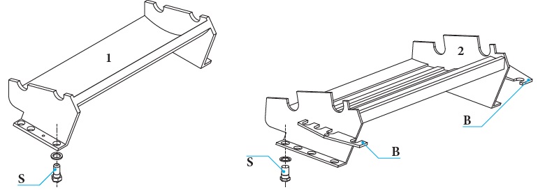
Replacing the fixed blade in the tractor's two-row chopper
1- Open the screws holding the blade (number 2 of the figures below).
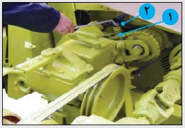
figure 1
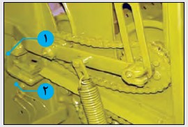
figure 2
2-Open the regulator piece (number 1 in the first picture)
3- Remove the part outside the center (number 1 of the second figure)
4- Remove the fixed blade from the right side of the machine.
5- To move the fixed blade in order to adjust the distance:
1-5- Loosen the screws on both sides.
5-2- Move the blade by rotating the off-center adjusting and measuring part on both sides of the machine.
5-3-Turn the cutting cylinder by hand and control the distance between the moving blades and the fixed blades.
Note: In self-driving choppers, there is no need to loosen the screw and it moves only by turning the levers on both sides of the fixed blade.
Opening and installing the movable blades of the cutting cylinder in the tractor's two-row chopper
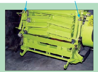
1- Loosen the screws of the top cover from both sides and then move it backwards with a circular motion. (Figure below)
2- Open the screws of the movable blade (number 1 in the figure below) and remove the blade. When replacing the movable blades, the cutting cylinder must be rotated by hand.
3- Be careful when installing new moving blades, they must be pairs and face each other so that the device is balanced.
4- Move the fixed blade completely to the back.
5- Adjust the distance of each movable blade from the fixed blade with two adjusting screws (number 2 in the above picture).
6-Tighten the screws holding the blade.
Pay attention: the adjustment of the moving blade in the self-driving machines is the same as the two-row machine, with the difference that there are no adjustment screws.
Safety: When adjusting the blades, be careful not to place your fingers in the path of the blades.
Click on the following links to view product images:
Sales of German KEMPER heads
Types of choppers behind the TINAZ tractor in Turkey
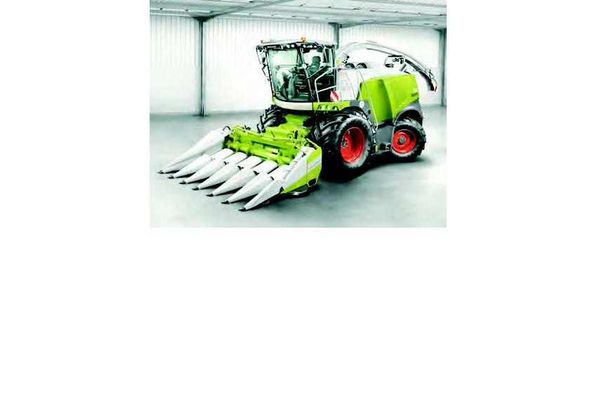
German Jaguar CLASS chopper-with German KEMPER head
Recent News